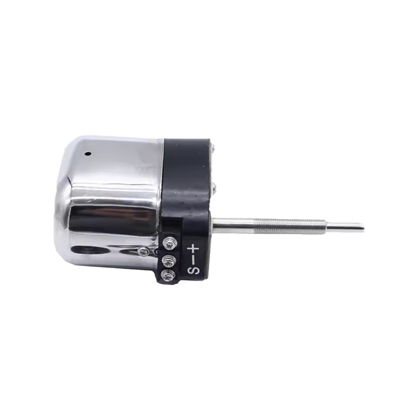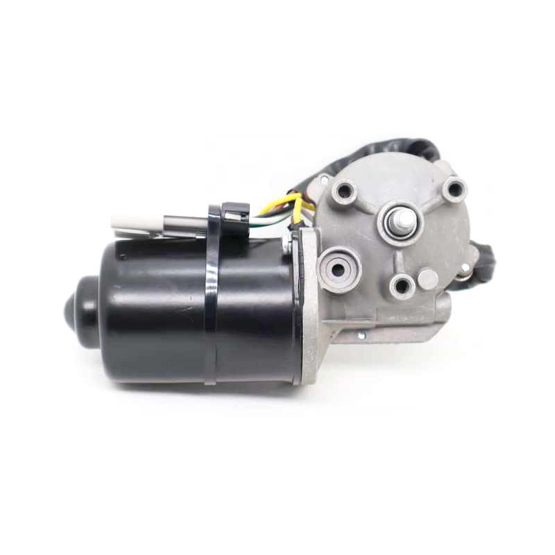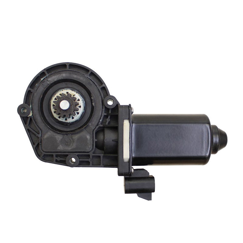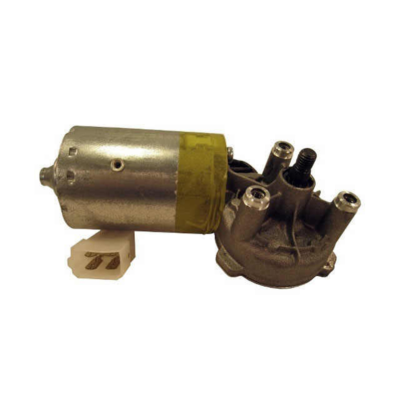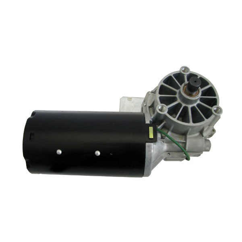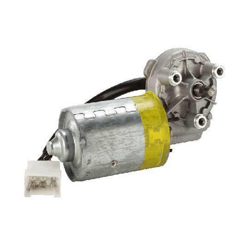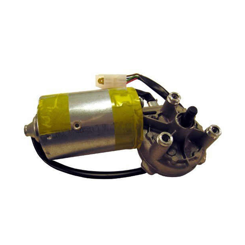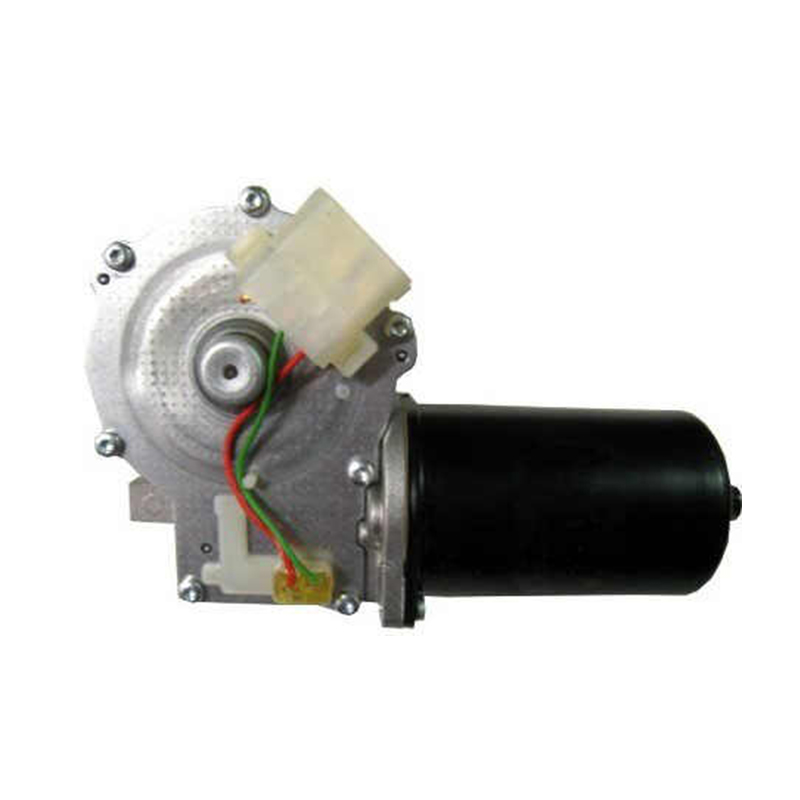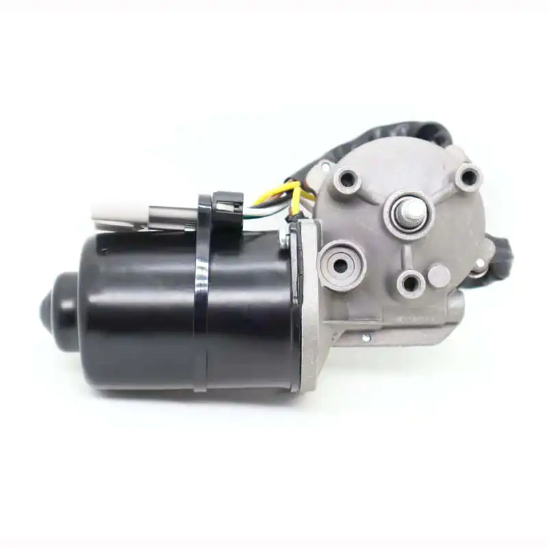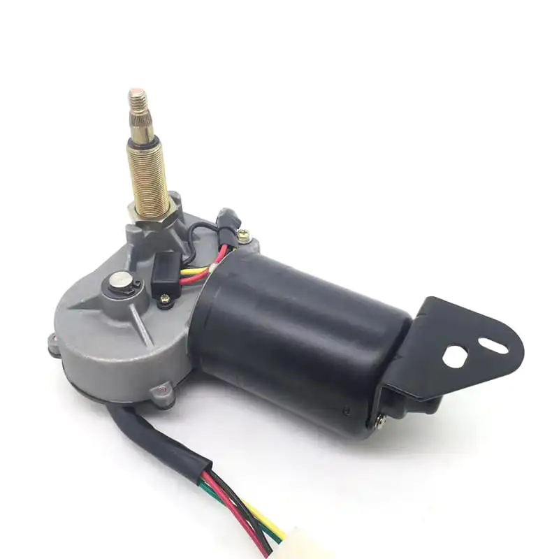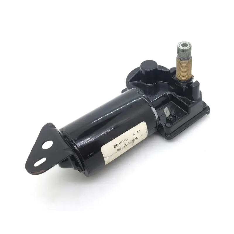
Replacing or installing a wiper motor sounds like a straightforward job until the connector comes apart and you're looking at a cluster of wires with no clear indication of which goes where. Even experienced technicians occasionally pause at this step, because wiring configurations vary across vehicle platforms, operating voltages, and control system generations in ways that aren't always obvious from the connector shape alone. Understanding how a Wiper Windshield Motor is typically wired, and why different configurations exist for different applications, resolves most of the confusion before it becomes a real installation problem.
Before breaking down specific wiring methods, it helps to understand the basic electrical anatomy of a wiper motor circuit, since all connection approaches share some common elements regardless of how many wires are involved.
Every wiper motor circuit manages a few core functions:
These functional requirements drive how many wires appear in the connector and what each wire is doing. Simple two-speed systems need fewer wires. Systems with integrated intermittent control or park circuitry need more.
Two-wire configurations are the most straightforward and appear on vehicles with basic wiper systems, older equipment, and some specialty applications where simplicity is valued over feature range.
In a two-wire setup:
Turning the wiper switch on routes power through the circuit, the motor runs, and interrupting that power stops it. No park function is built into the wiring itself, which means the wiper arm position when power cuts is wherever it happened to stop.
This configuration suits applications where precise park position isn't critical, such as certain agricultural equipment, older commercial vehicles, or retrofit installations where simplicity is a priority. From a troubleshooting standpoint, two-wire systems are easy to verify — if the motor runs with direct power applied, the motor itself is functional and the problem lies in the switch or supply circuit.
Three-wire connections are considerably more common in passenger vehicles and light commercial equipment because they add park circuit functionality. The third wire handles the automatic return to the parked position when the wiper switch is turned off.
Here's how the three wires typically divide up:
Without the park wire, wipers stop immediately when the switch is turned off, often leaving the blade in the middle of the windshield. The park circuit solves this by drawing power through a separate internal contact inside the motor until the cam or gear inside reaches the park position, then opening the circuit.
Three-wire systems are standard across a wide range of vehicles and are what most replacement motors are designed around when the application calls for clean park behavior.
Vehicles with two-speed wiper systems, typically a slow speed for light rain and a faster speed for heavy conditions, need at least one additional wire to support the second speed.
A common four-wire configuration breaks down like this:
Some motors achieve two speeds by using different internal windings, each supplied through its own wire. Others use a resistor in series with the low-speed supply to reduce current and slow the motor down. Which method a specific motor uses affects how the wiring is arranged and what happens if those wires are crossed.
Mixing up the low and high-speed wires won't necessarily destroy the motor immediately, but it will produce unexpected behavior, wipers running at the wrong speed for the selected switch position, which is a diagnostic clue worth knowing.
Intermittent wiper systems, which allow the delay interval between sweeps to be adjusted, introduce electronic control into the circuit. Depending on the vehicle's design, this control is handled either by a separate relay and timer module or by electronics built into the switch itself.
When an external module handles the intermittent function, the wiper motor itself may have the same three or four-wire connection as a standard system. The module sits between the switch and the motor, interrupting and restoring power at timed intervals. The motor doesn't need to know it's being pulsed.
Some wiper systems route additional signal wires to the motor for variable-delay control, where the module uses a speed signal from the motor itself to synchronize the pause interval with the wiper position. This adds wires to the connector and requires the replacement motor to have compatible signal output, not just the correct mechanical fit.
Swapping a motor in an integrated system without confirming signal wire compatibility is a common source of intermittent function problems after installation.
The park mechanism inside a wiper motor is worth understanding separately because it's one of the more commonly misunderstood aspects of wiper system wiring, and it's where installation errors tend to show up as operational problems.
Inside most wiper motors, a cam or contact switches internal connections as the output shaft rotates through each position. Near the parked position, this internal switch redirects current to keep the motor running briefly after the external switch opens, allowing the wiper to complete its final arc and land on the park stop.
When the park circuit fails or is wired incorrectly:
Testing the park function specifically, separate from basic motor operation, is worth doing before buttoning up an installation.
Most passenger vehicles run on 12-volt electrical systems, but commercial trucks, buses, agricultural equipment, and marine applications may use 24-volt systems. The wiring connection method is often similar in layout, but the motor's internal winding specification is different, and connecting a 12-volt motor to a 24-volt supply will damage it quickly.
Key differences to watch for:
For wholesale procurement and OEM applications, clearly specifying the operating voltage alongside other motor parameters prevents receiving a technically compatible-looking part that's rated for the wrong electrical environment.
Understanding the failure modes helps when diagnosing a wiper system that was recently worked on or when verifying someone else's installation.
| Wiring Error | Symptom | Likely Cause |
|---|---|---|
| Ground connection loose or missing | Motor hums but doesn't run, or runs erratically | Incomplete circuit preventing full current flow |
| Park wire not connected | Wipers stop mid-windshield when switch turns off | Park circuit open, motor can't complete return arc |
| Low and high speed wires reversed | Wrong speed at each switch position | Supply wires crossed at connector |
| Motor rated for wrong voltage | Motor runs very slowly or gets hot quickly | Voltage mismatch at supply |
| Intermittent signal wire absent | Delay function doesn't work, motor runs continuously | Signal wire missing or mismatched |
Running through this kind of quick diagnostic mapping helps isolate whether a complaint points to the motor itself or to how it was connected.
The wiring connection is only as good as the physical condition of the connector and terminals. Even a correctly wired system can have problems if the connector is worn, corroded, or improperly seated.
Checklist before completing the connection:
For vehicles or equipment in demanding environments, salt spray exposure, high humidity, or frequent washing, connector condition matters considerably more than it does in controlled environments.
For buyers sourcing replacement motors or specifying wiper motors for new builds, the wiring configuration needs to be confirmed alongside the mechanical specification.
Key points to verify:
For China wiper motor procurement specifically, working with a wiper motor manufacturer that can provide clear technical documentation, including connector pin assignments and circuit diagrams, reduces the risk of specification errors that cause installation problems in the field.
Wiper motor wiring isn't complicated once the logic behind each wire's function is clear, but the variety of configurations across different vehicles and operating voltages means assumptions are dangerous. Knowing whether the system uses two wires or four, whether the park circuit is internal or external, and whether any signal wires are part of an integrated intermittent control system makes the difference between a clean installation and a diagnostic job after the fact. For procurement teams, automotive engineers, and fleet maintenance operations sourcing motors at scale, confirming the wiring configuration as part of the specification process prevents the kind of compatibility issues that cause returns and rework. Wenzhou Junt Power Technology Co., Ltd. manufactures Wiper Windshield Motors for passenger, commercial, and specialty vehicle applications, with technical support available for wiring configuration verification and custom connector specifications for OEM and wholesale procurement. If your application involves a non-standard wiring layout or you need documentation to verify compatibility with an existing vehicle platform, sharing the connector specification and system requirements is a practical starting point.

Tel:+86-0577-66009580
Mobile: +86-18858801083
E-mail:juntmotor@126.com
Whatsapp:+8618858801083
WeChat: +86-18858801083
 WeChat

Automotive Reduction Motors Manufacturer

 +86-0577-66009580
 juntmotor@126.com
 Language
  English
 Português